- Alloy Steel — Quenched and Tempered.
- Individually Proof Tested to values shown, with certification.
- Proof Tested with 60% inside width special fixtures sized to prevent localized point leading per ASME A-952.
- Meets or exceeds all requirements of ASME B30.26 including identification, ductility, design factor, proof load
and temperature requirements. Importantly, these links meet other critical performance requirements including
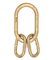
fatigue life, impact properties and material traceability, not addressed by ASME B30.26. - Forgings have a Product Identification Code (PIC) for material traceability, along with the size, the name Crosby
and USA in raised lettering. - Selected sizes designated with “W” in the size column have enlarged inside dimensions to allow additional
room for sling hardware and crane hook. - Crosby 1 ¼” to 2” 342/345 master links are type approved to DNV Certification Notes 2.7-1- Offshore Containers. These Crosby master links are 100% proof tested, MPI and impact tested. The tests are conducted by Crosby and 3.1 test certification is available upon request. Refer to page 147 for Crosby COLD TUFF® master links that meet the additional requirements of DNV rules for certification of lifting applications – Loose Gear.
- Incorporates patented QUIC-CHECK® deformation indicators.
| Size | A-345 Stock No |
Weight Each (lbs.) |
Working Load Limit Based on 5:1 Design Factor (lbs.) |
Proof Load (lbs.)** |
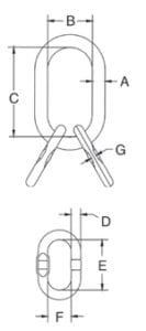
Dimensions (in.) |
||||||||
|---|---|---|---|---|---|---|---|---|---|---|---|---|---|
| (in.) | (mm) | A | B | C | D | E | F | G | Deformation Indicator |
||||
| 3/4W | 19W | 1014739 | 3.5 | 12300 | 28400 | .73 | 3.20 | 6.00 | .56 | 3.35 | 1.77 | .30 | 4.00 |
| 7/8W | 22W | 1014742 | 4.8 | 15200 | 35200 | .88 | 3.75 | 6.38 | .56 | 3.35 | 1.77 | .30 | 4.50 |
| 1W | 26W | 1014766 | 9.3 | 26000 | 60000 | 1.10 | 4.30 | 7.50 | .75 | 3.94 | 2.36 | .33 | 5.50 |
| 1-1/4W | 32W | 1014779 | 15.8 | 39100 | 90400 | 1.33 | 5.50 | 9.50 | 1.00 | 6.30 | 3.54 | .51 | 7.00 |
| 1-1/2W | 38W | 1014807 | 34.1 | 61100 | 141200 | 1.61 | 5.90 | 10.50 | 1.25 | 7.09 | 3.94 | .65 | 7.50 |
| 1-3/4 | 44 | 1014814 | 46.7 | 84900 | 169800 | 1.75 | 6.00 | 12.00 | 1.38 | 8.00 | 5.00 | .73 | 7.50 |
| 2 | 51 | 1014832 | 67.2 | 102600 | 205200 | 2.00 | 7.00 | 14.00 | 1.50 | 9.00 | 5.75 | – | 9.00 |
| 2-1/2 | 64 | 1014855 | 206 | 160000 | 320000 | 2.50 | 8.38 | 16.00 | 2.50 | 16.00 | 8.38 | – | 11.00 |
| 2-3/4 | 70 | 1014864 | 282 | 216900 | 433800 | 2.75 | 9.88 | 18.00 | 2.75 | 18.00 | 9.88 | – | 12.50 |
| 4 | 102 | 1014999 | 667 | 373000 | 746000 | 4.00 | 12.00 | 24.00 | 3.50 | 24.00 | 12.00 | – | 15.50*** |
* Ultimate Load is 5 times the Working Load Limit. The maximum individual sublink working load limit is 75% of the assembly working load limit except for 2-1/2”and 2-3/4”, which are 100% of assembly working load limit. Applications with wire rope and synthetic sling generally require a design factor of 5.
** Proof Test Load equals or exceeds the requirement of ASTM A952(8.1) and ASME B30.9. *** Sublink only. For use with chain slings, contact Atlantic Cordage for proper master link selection.